Anet A8 marlinification
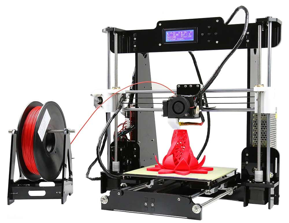
I had an Anet A8, it was the cheapest 3d printer in the market around the time that I bought it (2019) and served its purpose well enough, but now with the pandemic lockdown I have enough time to invest in some upgrades and some learning.
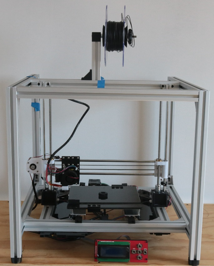
First, I dissasembled the chasis and make my own with aluminium extrusions, doing a cubed shape.

Here are the CAD files.
Design
The first objective in the project is to build a stiffer frame that is easy to enclose without invest too much time in making new parts to get the printer working, as it will be done anyway in the future when changing the controller and mechanical principle.
Aluminium frame
One of the main weaknesses of the AnetA8 is the acrylyc frame, which is not rigid enough to withstand high speed/torque, brittle, and difficult to enclose. As i had a good time making a table with T-Slots aluminium profiles i thought why not?.

The criteria were:
- To make a box so it would be easier to build and enclose (probably more expensive tho).
- Big enough to fit the Anet parts.
- To use the profiles without cutting them.
I decided to use 30x30 T-Slots as they are cheaper and stronger than 20x20 V-Slots, which are also a good option to make machines too as there are plenty of accesories and also works as transmission system, but i am not going to make any changes in that last topic yet.
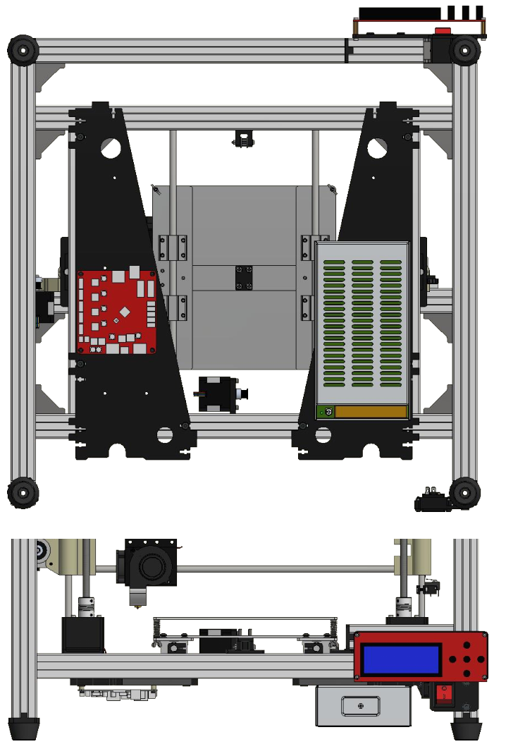
As the beams are sold in multiples of 250 mm and the Anet axis are longer than that i chose to use 500 mm profiles in the following design:

There is some space in the bottom to separate the electronics and power from the rest of the machine, wich will be in an enclosure in the future. The joints are corner brackets, you can add more or other type of joints to increase stiffness, i used the minimum as the enclosure will also help. The z axis rods are held by SK vertical supports. Unfortunately, there are four of the beams that must be cut to a different length, one of them is to hold the spool, other one for the screen, and the other two will support the z motors and define the length of the y axis.
I could have made the y axis longer by simply not cutting these pair of profiles, but then i will have to buy new 8 mm steel rods, belt and bed system, so nah. I am planning to make a corexy anyway. Fortunately, i had a 1.5 m aluminium profile that i did not use in my table, so i cut it to make these beams and an extra 500 mm.
The foots are standard 30x30 T-Slot rubber foots with a 3d printed piece for attachment to the beams.
Finally, these are the parts:
| Item | Quantity |
|---|---|
| T-Slot 30x30x500 mm | 12 |
| T-Slot 30x30x340 mm | 2 |
| T-SLot 30x30x120 mm | 2 |
| SK8 shaft support seat | 2 |
| Corner bracket | 22 |
| Rubber foots | 4 |
| End Cap foot attachment | 5 |
NOTE1: The extra printed attachment is to cover the sharp corners of the aluminium profile that hols the screen.
NOTE2: The small beams could be smaller, like 3 cm smaller.
NOTE3: That extra beam for the LCD is temporal, as it will be held by the enclosure in the future.
3D Printed parts
As i dispose of the acrylyc frame, i had to design and print parts to hold and support some components. The idea was to make them small as possible until i get the printer working. The printed components are:
| Item | Quantity |
|---|---|
| Spool holder joint | 1 |
| Spool holder nut hanlde | 1 |
| Spool holder cone | 2 |
| Y Axis rod holder A | 2 |
| Y Axis rod holder B | 2 |
| Y Axis pulley support | 1 |
| Z Motor holder | 2 |
| Y Motor holder | 1 |
| Z Endstop mount | 1 |
| Y Endstop mount | 1 |
| X Belt attachment | 2 |
| Y Belt attachment A | 1 |
| Y Belt attachment B | 1 |
| Rocker Switch mount | 1 |
| Power inlet mount | 1 |
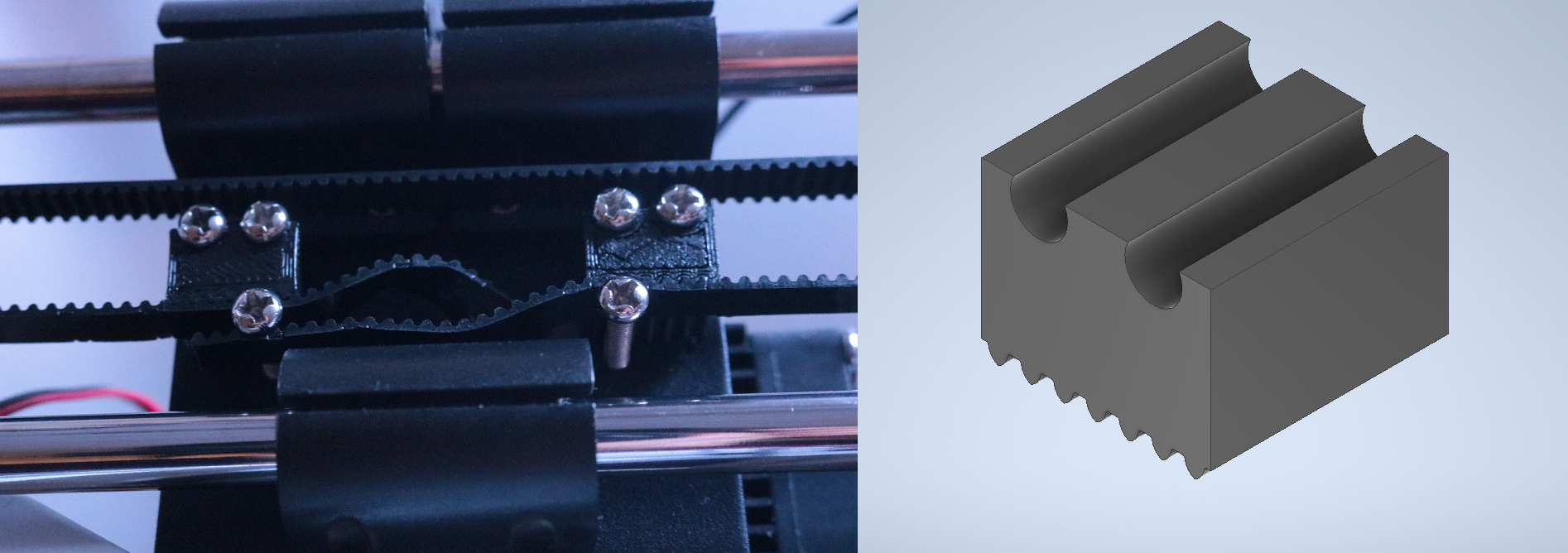
The x belt attachments were made as the previous system (bolts and zip ties) is awful, these are not too fancy either, but will stand long enough until i change the extruder for something else.

The y belt attachments were made as the height of the belt with respect to the y carriage changed.
The other parts of the spool holder are on my Thingiverse, aswell as in this repository, except for the piece that joint the spool holder with the frame.
Electronics
To hold the electronics the idea is to add a sheet of acrylic with mounting holes in the bottom face of the frame, but that will be done with the rest of the enclosure, so for now i will use the original parts of the anet where the electronics is mounted on, which attach really fine to the T-Slots and make everything easier, except for the inaccesibility of the SD port… well, is not difficult to make new holes to put the board closer to the edge or just USB print meanwhile.
I also reused one of the acrylic panels to hold the LCD.

Manufacturing
Disassembly
All the acrylyc frame was dispossed with the exception of the panels mentioned before.
All the other important parts were used, but the bearings that tightens the y belt were replaced with a proper GT2-16 idle pulley, which is also a good idea for the x belt, but there is not enough room.
Cutting the profiles
I cut the 1.5 m profile with saw and then rectified the faces using a Tormach. The length has to be as accurate as possible and the faces must be flat to get a decent joint.
Printing
All the part were printed with 0.3 mm layer height, 3 shells and 30% infill, no support nor raft, with exception of the z motor holders. These are the orientations:
Drill bits with the right dimensions were passed through all the holes in the pieces once they were printed, to clean.
Extending wires
Some of the wires had to be extended due to the new position of the controller, these were:
- X endstop
- Extruder motor, fans, thermistor, heat cartridge
- Z endstop.
I had a power socket previously installed in the printer with a rocker switch, if you want to do this you will have to wire it like this:
(image)
Assembly
Frame
To assemble the profiles it is necessary to have a good square set and flat surfaces to get the joints perpendicular.
The first step is to attach the corner brackets (not too tight until the end) into every profile with bolts (M5x12) and nuts, you can use other profiles to help you with.
Then, assemble the “sides”
The inside. Use a caliper to get the distances right.
Put the sides in the inside.
The upper profiles.
Finally, the spool holder, but you can put it after all the other steps so it doesnt bother when wiring.
Be sure that the bolts are tight.
Y Axis
The motor in its holder then into the frame. Attach the motor loosely to then use the slotholes to tighten the belt.
The pulley support.
Put the shafts in the bed carriage and then into the rod holders.
This assembly into the frame.
The y endstop support.
The belt in the attachment and around the pulleys, and then tighten with the motor holder slotholes.
X Axis
The belt attachments and bolt (loosely).
The shafts faces must be aligned with this side of the right support.
Put the belt through the bearings, the motor, and then into the attachments. Fasten the bolt.
Z Axis
Put the motors (with the couple) in the holders, also bolts and nuts to attach to the profile.
Pass the shafts and ACME thread through the bearings and nut.
Put the assembly on the motors, fasten the set screw on the couples.
Attach the SK8 to the shafts and frame.
Attach the z endstop support (loosely).
To align the x axis, you can move the gantry all the way up in the z axis and compare the amount of ACME thread coming up from the nut and adjust.
Electronics
Use M3 bolts to attach the power source to one of the large acrylic panels, put M5x8 bolts and nuts in the indicated positions (yes, they fit right in).
Use M3 bolts and nut and plastic separators to attach the motherboard to the other acrylic panel. Put the M5 bolts in the same positions as the previous step.
Attach them to the frame.
Connect everything as it was.
The wires were wrapped around with spiral wire wrap tube.
Done(?)
Remember to level the bed. In my printer i also have a glass bed from an Ender3.

Enclosing
Finally, using some aluminium/foam sheets I enclosed the volume and replaced the controller with an Arduino MEGA/RAMPS combo. All those file are lost forever :c (in my old laptop), but I made a nice video of the printer and there are some pics in my Instagram.
