T-Slot Workbench
Summary
I made a simple T-Slot table, it makes me really happy because i finally have a place to work in my small apartment :D. It may be a little expensive (170 dollars buying the parts from the local store (in Chile) instead of aliexpressing them, without the plank or the 3d printed parts), but if you are not happy with it you can always disassemble it a made another project with the parts, all hail the modular construction systems!
The updated parts are HERE
Description
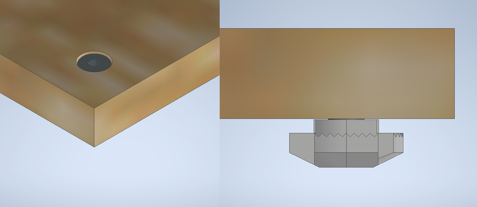
It has a plywood top (150x56x1.2 cms) bolted in an aluminium frame made with 30x30 t-slot profiles and accesories, also some 3d printed parts. The surface stands 77 cms above the floor. The bolt head surface is coincident with the top surface.

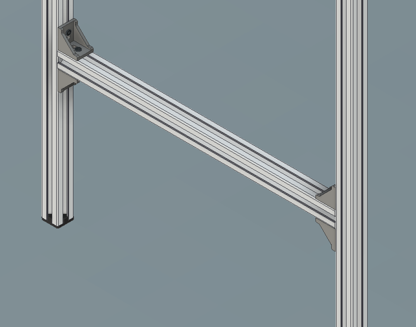
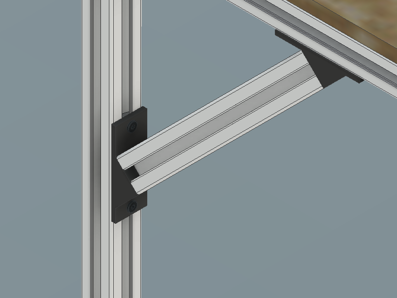

I 3d printed the caps and the 45 degree brackets, as my local store did not sell them, the files are included in the parts folder. The foots could have been an adjustable level mechanism but i did not really need that, so i put caps in there, aswell as in the ends of the 1500 mm profiles to avoid getting cut.
BOM
| Item | Quantity |
|---|---|
| Plywood plank | 1 |
| T-Slot 30x30x1500 | 2 |
| T-Slot 30x30x750 | 4 |
| T-Slot 30x30x500 | 4 |
| T-Slot 30x30x250 | 2 |
| Corner bracket 30x30 | 16 |
| 45 degree bracket | 4 |
| Tslot 30x30 cap | 8 |
| Drop in M5 T nut 30x30 | 54 |
| M5x12 flat head bolt | 42 |
| M5x15 flat head bolt | 12 |
| M8x16 socket head bolt | 4 |
The tools needed are:
- 3 mm allen wrench
- 6 mm allen wrench
- Rubber hammer (maybe)
Manufacturing
Plywood top
I made the plywood top using a CNC, so it was really easy. It has 12 holes and pockets, to put the bolts and fit their heads. I could have used countersink bolts, but i had some flat heads that were ok. If you want to use another kind of bolt (or a top with a different thickness) remember to adjust the pocket to fit the head and use the right length to attach to the T nut in the aluminium frame.
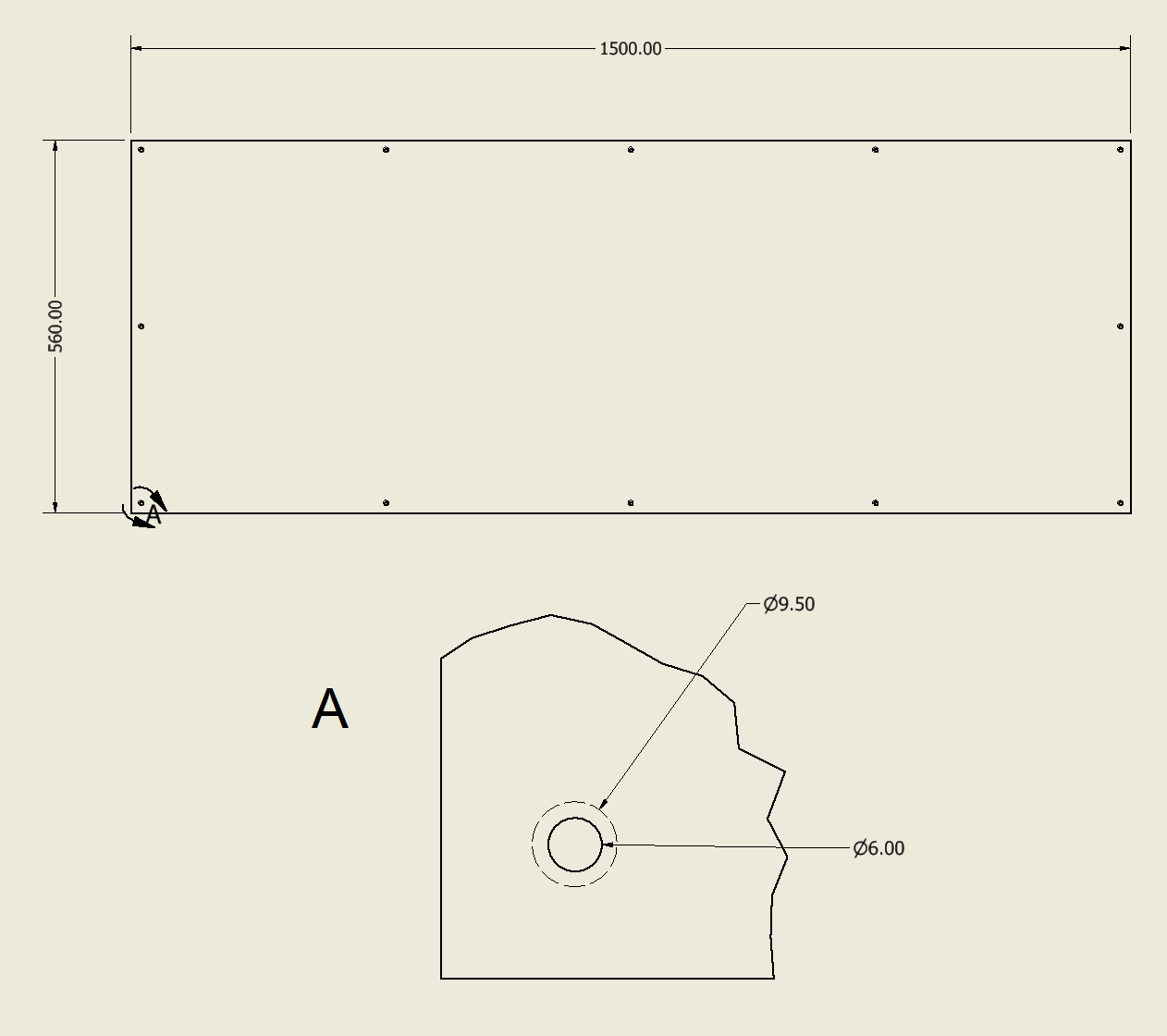
You dont really need a CNC as it is just a square with holes, which are 6 mm to allow a M5 bolt to pass through it and some play.
3D Printing
I used the caps from this file in Thingiverse.
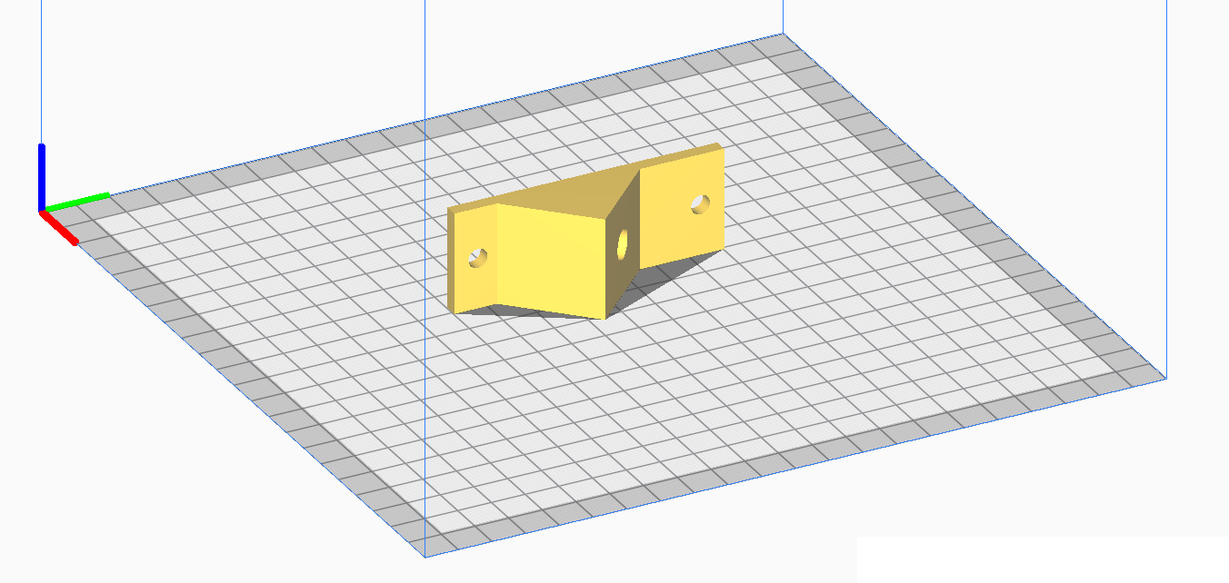
I designed the 45 degree bracket to be bolted with a M8 socket bolt into the ends of a 30x30 t slot, you can get it from the parts folder or from my Thingiverse.

It has to be printed this way so the face where the aluminium profile is bolted be flat. No supports or raft needed.
Assembly
There are four possible sub assemblies to start with: Top assembly, leg assembly, leg stretcher and diagonal stretcher.
It is very important that the aluminium profiles are correctly aligned, so use a set square and a flat surface to help with it.
The t nut emm… ears? should be perpendicular to the profile direction to get a better grip.
Top assembly
- Insert the bolts in the holes of the plywood, the thread must be barely inside a T nut.
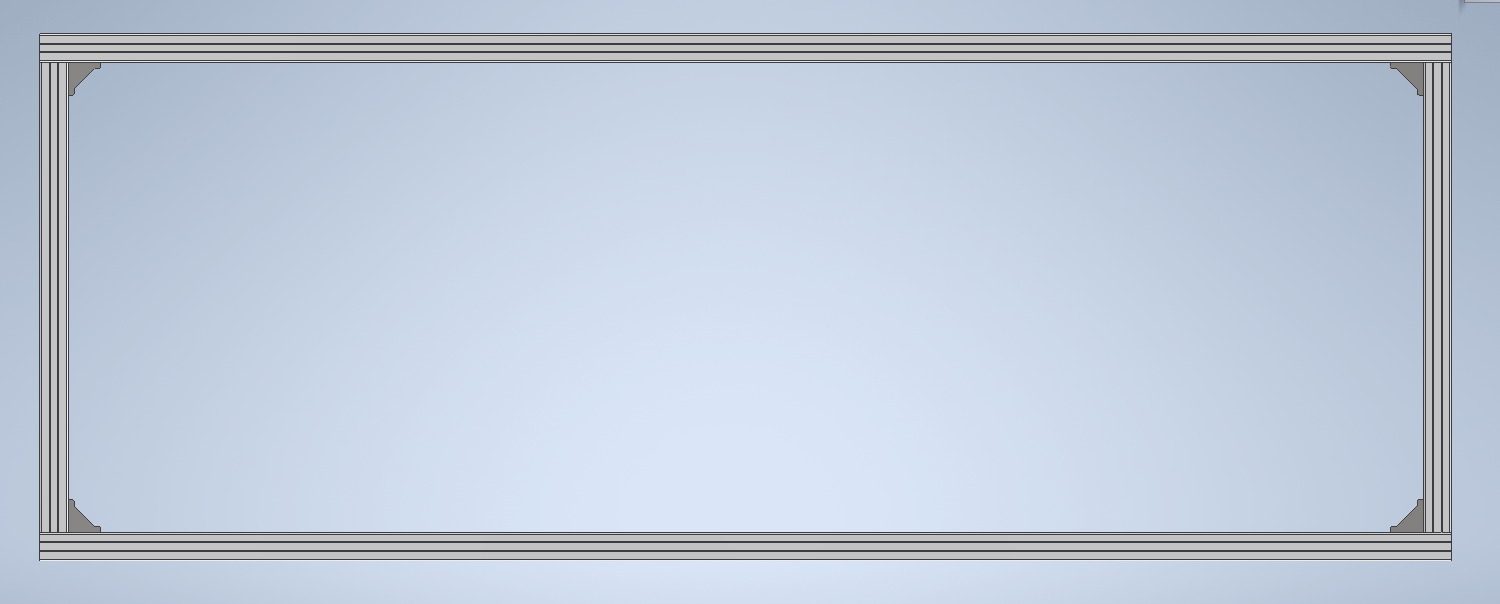
- Assemble the aluminium frame as the pic indicates, with 2 1500 mm and 2 500 mm profiles.
- Put the plank with the bolts on top of the frame and move the bolts around until they drop inside the rails.
- Tighten each bolt.
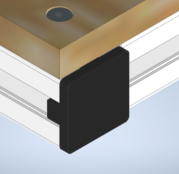
- Put the 3d printed caps in the ends of the long aluminium profile, this is optional. A rubber hammer may help if the piece does not snaps inside easily.
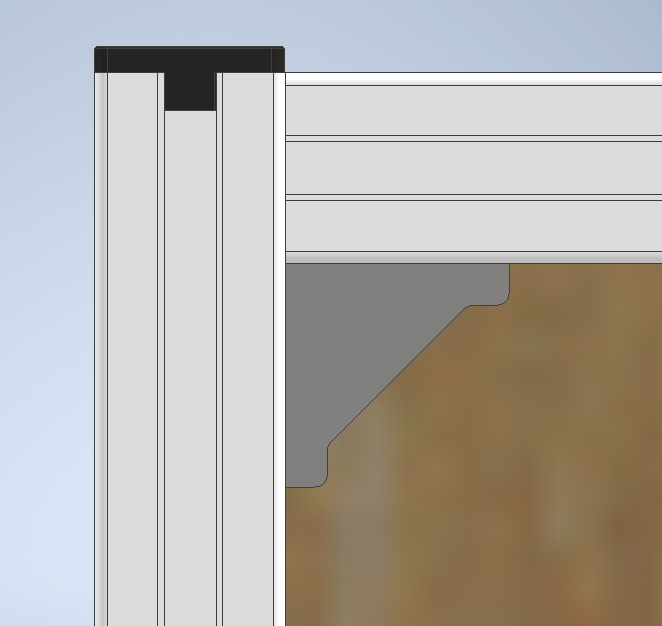
The inside brackets are not really helping anymore, so you can remove them to be used in the next steps.
Leg assembly
- Put a cap in the end of a 750 mm profile. (Or a level mechanism if you got one)
- Add two adjacent corner brackets at the other end (with bolts and nuts). The unocuppied surface of the brackets must be coincident with the face of the profile.
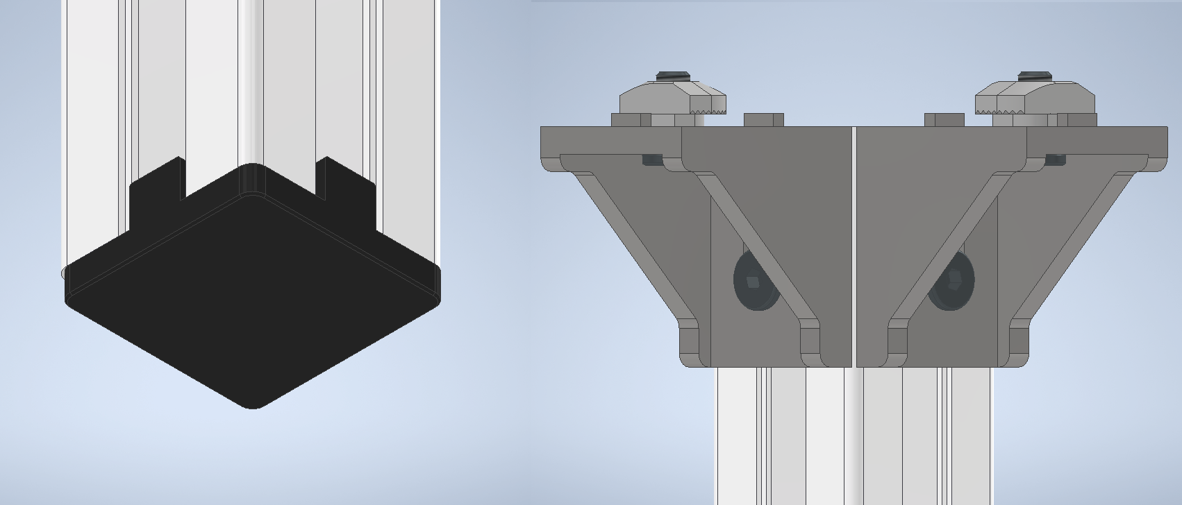
- Repeat the process 3 times to get the four legs.
Leg stretcher
- Put two corner brackets in opposite sides in both ends of a 500 mm profile
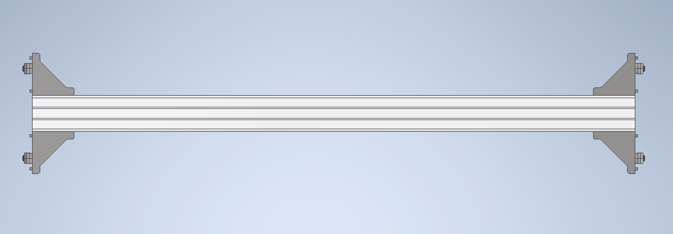
- Repeat the process one more time with another 500 mm profile.
Diagonal stretcher
- Put a M8 bolt in the center of the end of a 250 mm profile, try to thread it straight inside with a wrench, this will form the inner thread in the profile hole.
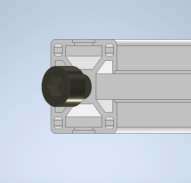
- Repeat the process with the other face.
- Bolt a 45 degree bracket to each face of the aluminium profile as the pic indicates.
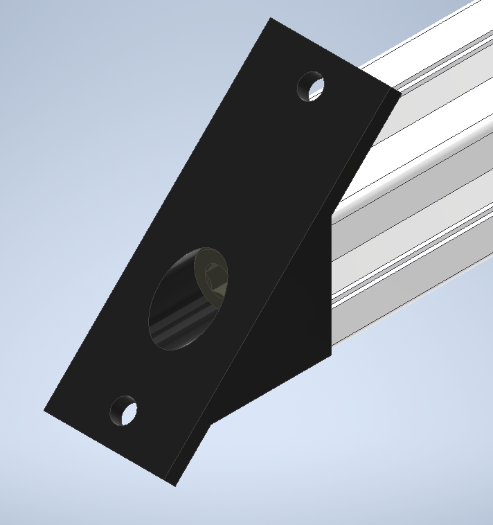
- Add the M5 bolts and nuts.
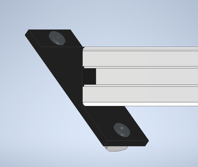
- Repeat the process one more time with another 250 mm profile
Side assembly
- Using the brackets in a leg stretcher assembly, bolt it to a leg assembly 250 mm above the end cap in the leg, as the pic indicates.
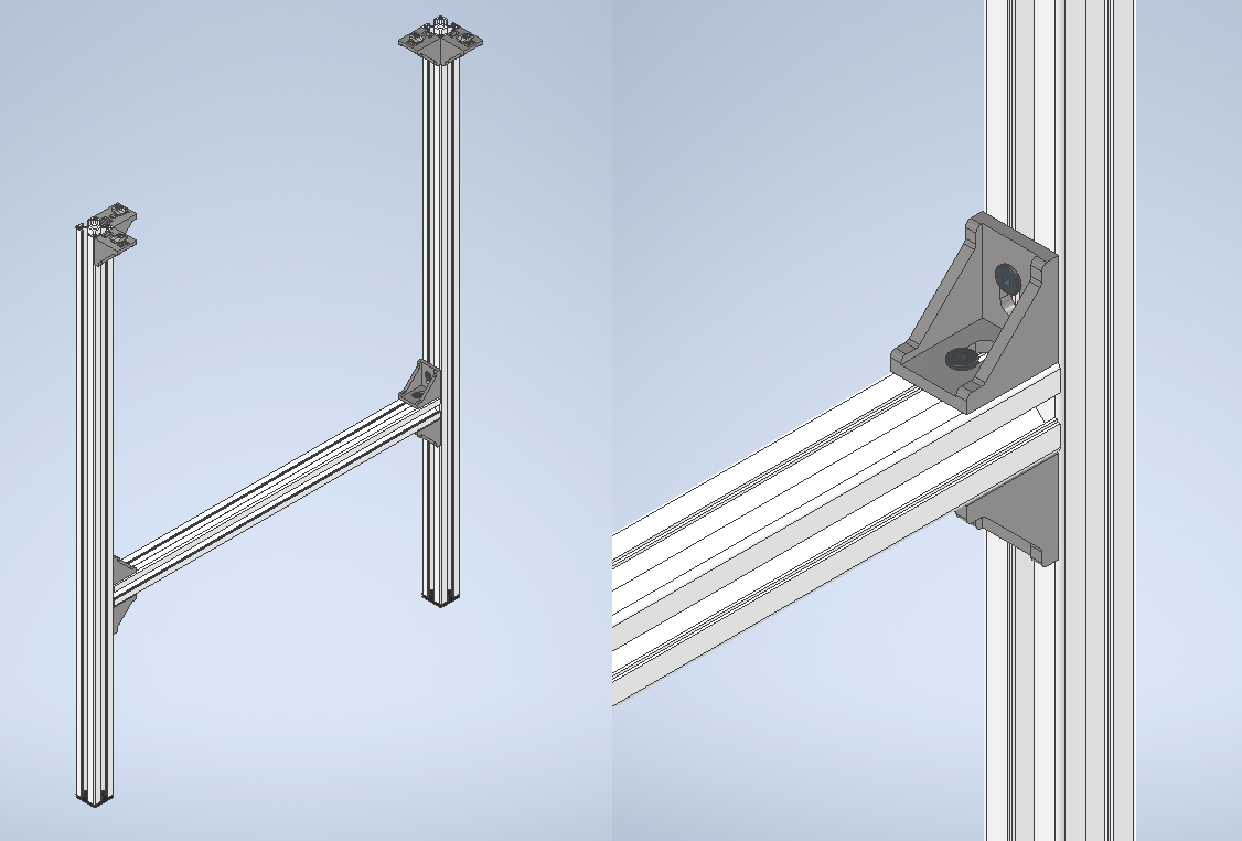
Repeat with other leg, two brackets must be facing inside and the other two must be pointing at the same direction.
Repeat the whole process one more time to get another side assembly.
Full assembly
- With the top assembly facing downwards, bolt the side assemblies in the corners of the aluminium frame with the brackets.
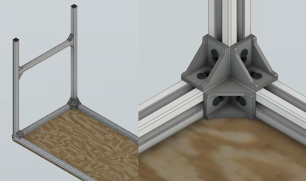
- Bolt the diagonal stretchers as close as possible to the corner. One of the bolts may be tricky to tighten as it’s head is too close to the profile, but is still possible with a small or rounded wrench.
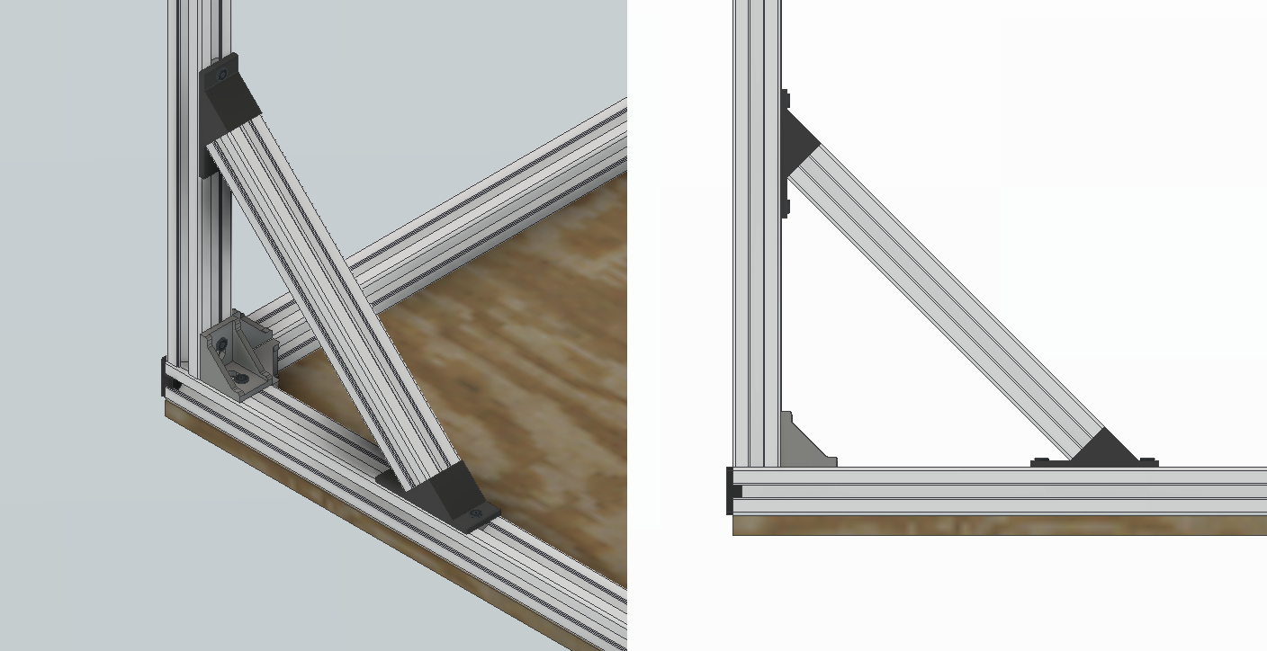
- Turn it upside down, of course.
DONE

Now you can add more features to your table, i 3d pritned a headphone stand and attached to it. A cool thing is that you can disassemble it and bolt it togheter to reduce it’s volume when you have to move, maybe form some handles.
